We remain fully operational. Our teams are working around the clock to ensure your deliveries continue safely.

DOWNLOAD THE APP


Customer Services
Copyright © 2025 Desertcart Holdings Limited
DOWNLOAD THE APP


⚡ DIY Tesla Coil: Ignite your curiosity and light up your world!
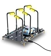
The PEMENOL Tesla Coil DIY Kit is a hands-on educational tool designed for college and university students to build a functional plasma arc generator. It produces impressive 10-15cm electric arcs capable of wirelessly lighting fluorescent and neon tubes. Ideal for physics teaching, STEM projects, and tech competitions, this kit sharpens soldering skills while delivering a stunning visual experience. Note: Requires prior soldering experience and an external 12V-36V power supply.


| ASIN | B092TZ9K3J |
| Best Sellers Rank | #93,830 in Toys & Games ( See Top 100 in Toys & Games ) #1,005 in Educational Science Kits |
| Customer Reviews | 3.4 3.4 out of 5 stars (166) |
| Item Weight | 2.05 pounds |
| Item model number | GY19206 |
| Manufacturer | PEMENOL |
| Manufacturer recommended age | 24 months - 20 years |
| Package Dimensions | 11.02 x 6.06 x 3.62 inches |
P**P
disappointed , wasted time
the components list said 12 pc 45uf capacitors but only were 2pcs 45uf and 11 pcs 35uf capacitors that are not on the components list , the instructions have no wiring diagram or ledged , the package was not good and looked like it was seriously rattled , many times . I repackaged it nicely but I would not accept the components being different from the components list
S**0
Bad transformer. Missing wire. Instructions were not for tge pieces delivered
This kit is easy to build. But the instructions were incorrect for the parts that were delivered. The wire they said was in the kit was not supplied. After completing the build it would not work. There was no support from the company for my questions. I tested and replaced parts and found thy transformer that was supplied in the kit was bad. I replaced it with one of my own and everything works now. To expensive of a kit to be supplying my own parts. Especially the transformer which is the most expensive and important part of the kit.
Z**U
No Instructions Items. You need to get the link download and may need more wire.
Not a bad product, some of the instructions aren't as clear and you have to download them. I think the company puts a piece of paper with a barcode link you can scan to download the instructions digitally. You will need a power supply. Review Ohms law if you are not familiar because the instructions don't give exact detail about how much voltage the circuit boards with resisters and capacitors can handle, so be wear and take caution. I had to purchase more wire because the wire you are given and the measurements in the instructions that it calls for is definitely less. Pemenol's Customer services is good. I would give four stars but it was quite a hassle getting through the confusion of the instructions. Could just be to language barrier. Not bad for a DIY project. Parts could be a little better.
D**N
This Tesla Coil Kit: You can hear the sparks!
This is has a very bright spark gap, and it's loud. You really know you are working with some power when it is operating. First, soldering is required. It's easy, it's fun, but if you don't know how then order a learning kit at the same time and build it first. Also, look for online instruction and videos in addition to the learning kit. I built half of mine with lead-free and the other half with leaded solder for practice. You will need hot melt glue. You do not have to use hot melt glue but gluing sure is fast and easy if you do. You will need a way to scrape or sand a little enamel insulation off of some wires. Finally, you will need a way to put some small holes through micro plywood. I suppose punching might work, but drilling is easy and accurate. I think there was enough wire in the kit to build it, but it was easier and cheap to add some solid conductor of my own. I used 18ga, which seemed about right for building the capacitor bank and as a longer ground wire. Again, all of the parts were easy, with no super tiny soldering connections. I'll start with what I had to go back and redo. I did not notice that the two ends of the main coil are finished differently. One has a wire that wraps over the end of the coil. This wire needs to be in contact with the stainless steel ball. There is no need to remove insulation; you will have all the volts you need to punch through the enamel on the wire. The other end of the coil has the wire that you thread down through a hole that you made in the upper micro plywood. This end will need to have some enamel removed because you will be soldering it. The second mistake I made was how I built the capacitor bank. The thin resistor leads will not handle the current and actually glowed orange in a dark room. That was pretty cool looking, but I knew I had to add heavier wire. The manual showed the capacitor leads bent over and soldered to the next capacitor. I decided it was a bit cleaner at that point to add some of my 18ga Cu wire, and it worked great. One more item, my flyback transformer had fewer pins than the one in the manual. I followed their pictures for which wire to connect where and it worked The instructions indicate an optimum voltage of about 19VDC at up to 80watts. 80 W divided by 19V = 4.2 Amps. There are plenty of 12VDC power supplies that will power it. You can also use a 12VDC gel cell, or car, or motorcycle battery. Interestingly, a little bit stronger laptop power supply is perfect and low cost on Amazon. Many of these are around 19V at up to about 4.2A. Higher amps are OK, so are higher volts. The instructions indicated 12 to 36VDC, 60 to 80W. For operation, I mentioned that it is loud. You will easily be able to hear it in an average bedroom or classroom. The brightest spark is the spark gap. I think the circuit uses power transistors to oscillate, providing alternating current to the first step-up transformer. The spark gap is a tunable high-power way to generate the high frequency and high power used to drive the main coil. The first test I did was to check for noise on an AM radio tuned between stations. It was pretty fun to hear a friend on a cell phone tell me they could listen to me clicking the kit on and off 200 ft away! I guess this might operate similar to an early Marconi transmitter. You are probably wondering if you can feel the voltage. I could, it was unpleasant, so I avoided getting too close to the output. The answer depends upon the frequency, and in a kit, the output can be a combination of high and low frequency. High enough frequency, and you cannot feel it. Lower and you do feel the electricity. But do not touch the spark gap when it is operating. When you see the bright spark and hear it, you won't want to. However, the main output coil can produce big, long sparks but be difficult to feel when there is no low-frequency energy in it. Regarding the voltage, I could make a fluorescent light fixture tube glow up to about 3ft away. I would keep sensitive electronics away from it. I used a cell phone for the pictures, and it worked well. Regarding the pictures, you should be able to hear the spark superheating a thin thread of air. There are two types of high voltage phenomena producing light. First, the air is an insulator; the electrons are tightly bound to the atoms. Think of voltage as pressure, or push force. When the voltage is high enough, it forces electrons to flow, producing the lightning spark you see. This review will get way too long if we explain all of the interesting concepts, so I'll stop here. I used 1-2-3 blocks from Amazon to aid in constructing the spark gap. You can't adjust the gap when it's running, but that's where you tune it. So plan for access later. For the capacitor bank, I hotmelt glued the caps together, then soldered the interconnecting wires, then hotmelt glued the module to the provided board. As mentioned above, do not rely only on the resistor leads for capacitor interconnection, as my picture shows. Do as the kit instructions show and use capacitor leads, or add your own heavier wire and solder the connections. I had my reservations about gluing to the end-grain of the dowels. After some research, I discovered that some people recommend hot melt glue for end-grain, and it worked! I'm careful when handling the device, but so far, no problems. Besides, I built it; I can re-glue it if I ever needed to. Although this has modern parts, it is kind of easy to imagine working in an old wooden laboratory with Tesla, in a darkened room where you can see the sparks better, and with the sounds of high voltage. It inspired some online research where I learned some things and had fun doing it.
A**Y
The Unfinished Symphony: A Review of the Tesla Coil DIY Kit
The enigmatic Tesla Coil! A testament to the audacious dreams of a maverick inventor, promising to illuminate the world with wireless power. And now, intrepid tinkerers, the opportunity to construct your own miniature marvel awaits! The PEMENOL Tesla Coil DIY Kit beckons, a gateway to the electrifying realm of electromagnetic induction. But before embarking on this scientific odyssey, a word of caution is prudent. A Project for the Adept Assemblers: This is no mere child's plaything. The kit arrives in a state of beautiful potential, a collection of parts awaiting your soldering expertise. While the instructions assure that the process is straightforward, a shaky foundation in the art of solder will leave you stranded on a sea of uncooperative wires. Be warned, this is a project best suited for the seasoned electrician or the determined student with a thirst for knowledge (and a hefty helping of soldering practice). A Spark of Genius, a Hint of Frustration: Imagine conjuring miniature bolts of lightning at your fingertips! The Tesla coil, when complete, promises a dazzling display of high-temperature plasma, capable of igniting fluorescent lamps and mesmerizing onlookers. The 10cm arc of sparking fury is a sight to behold, a testament to the ingenuity of the original inventor. However, a dark cloud looms on the horizon – the kit itself falls short of the grand vision. The Incomplete Equation: The PEMENOL kit, like an unfinished symphony, lacks crucial components to complete the masterpiece. The provided copper wire and 12-gauge insulated wire are woefully inadequate for the task at hand. Those embarking on this electrical escapade must be prepared to source additional materials – more copper and more 12-gauge wire – to bring their Tesla coil to life. Consider it a test, a minor hurdle to overcome on the path to scientific enlightenment. A Flawed, Yet Fun, Endeavor: Despite its shortcomings, the PEMENOL Tesla Coil DIY Kit offers a thrilling glimpse into the world of electrical phenomena. For the tenacious tinkerer, the challenge of assembly and the satisfaction of sparking a miniature lightning storm are rewards enough. Just remember, this is a project best approached with a well-stocked toolbox, a thirst for knowledge, and perhaps a healthy dose of ingenuity. In Conclusion: The PEMENOL Tesla Coil DIY Kit is a curious contraption – a spark of genius held back by a lack of materials. For the experienced hobbyist, it's a weekend project brimming with potential. For the novice, it's a crash course in electrical engineering, albeit one requiring a trip to the hardware store. But for those with a spirit of adventure and a soldering iron in hand, the PEMENOL Tesla Coil DIY Kit offers a unique opportunity to unlock the secrets of electricity and create a dazzling addition to your collection of scientific oddities.
Y**U
looks good, bigger than I imaged, with detail instructions and many big capacities. haven't start to solder it but hope I have good luck.
C**N
Il y a beaucoup des pièces manquantes. Très déçu
C**D
The instructions clearly have been translated from another language to English through google translate. For example, here’s step 7: «Treatment a Coil Inductor» Another example is where I’m still trying to figure out the meaning. Step 12: «Reserved the left pin which marked ‘-‘ next red case and remove another pin». Do they want me to remove the positive pin from the flyback transformer?? Another thing to consider before buying is that you’ll need a high wattage soldering iron to solder most components because the board itself works as a heatsink, which makes it almost impossible to solder properly with the average solder iron (It creates cold joints).
Trustpilot
1 day ago
5 days ago