We remain fully operational. Our teams are working around the clock to ensure your deliveries continue safely.

DOWNLOAD THE APP


Customer Services
Copyright © 2025 Desertcart Holdings Limited
DOWNLOAD THE APP
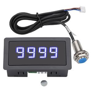
🔵 Precision Meets Performance: Own the RPM game with EEEkit’s sleek digital tachometer!
The EEEkit 4 Digital Blue LED Tachometer is a compact, high-precision RPM speed meter featuring a wide 10-9999 RPM range and 0.1% accuracy. Its bright 4-digit blue LED display ensures easy readability, while rapid response frequency (>3 times/second) keeps you updated in real time. Powered by advanced A/D conversion and stable IC components, it offers reliable performance and remembers your settings after shutdown. Ideal for conveyor belts and motors, it also supports multiple sensor inputs for voltage, current, temperature, and more, making it a versatile tool for professional-grade speed and physical quantity monitoring.


| Brand | EEEKit |
| Item Weight | 0.09 Kilograms |
| Item dimensions L x W x H | 4 x 8 x 2.5 inches |
| Manufacturer | EEEkit |
| Material | Plastic |
G**Y
Works as advertised, very good value
Price is one of the best I found. No instructions are included, however the pictures on Amazon give a wiring diagram.. This is necessary because the "printing" on the case is almost too small to see. Plenty (actually more than enough) wire length is provided. Using this is quite valuable for me, the previous (from the factory) minimum speed was around 650 RPM, using this RPM indicator as a reference I was able to modify the speed drive to lower my minimum speed to near the 500 RPM I desired. Also I was able to see how fast this machine would go if the max speed stop is bypassed. The display can be mounted in a "project box" for a more professional appearance. (The current installation is temporary, and I haven't done this yet). The photos show my "temporary" installation". Demonstrating the device works as advertised. I assume it is accurate, although I do not have a standard to compare it to. RPM indications (in photos) show the limits of the machine (normal speed controls overridden to achieve top attainable speed). One slight negative, the display does not give "instant" response. Once speed changes it takes about a second to update. This isn't an issue but I felt obligated to point this fact out in the review.
Z**K
Great and hackable
If you look at the circuit board there are places where extra buttons can be soldered in. Do this and you get a preprogrammed set of goodies. Stop watch, speed count, slower count, number stuff and stuff. 9 of the stuffs. If you have a temp probe the right Ω then it has a stuff for that too already programmed and ready to use, just need a button.. worth the price, every penny..
P**N
Simple inexpensive tachometer
This is a convenient device for providing speed readout on a machine tool. I printed a snug fitting collar for the end of the lathe spindle with a pocket for the magnet which was glued in place (be sure to check polarity first). A small box holds the board and display, a switch, and a 9V battery. The listing and photos have contradictory statements regarding voltage requirements, and the label stated 12-24V , but 8-24 seems to be correct. The device activates at a little over 8V. An aluminum bracket for holding the Hall sensor was attached to the back and that was it. The readings were accurate based in comparisons to a laser tachometer, and the display is fine and reasonably stable after a few seconds (the actual image is better than in the pictures because I just used a cell phone). Overall, this is a nice addition for 18 bucks. I subtracted one star because of the poor documentation. It is apparent from the reviews that many people found the hookup to be difficult. I believe it is actually very simple but needlessly confused by the bad description. One problem is that the connector wires are all white with red markings on the back to distinguish them. However, the photos show only the all white side. Since the plug can only be inserted one way, if the colored sensor wires connection to the labeled-side connector wires was shown in a single photo it probably would have eliminated all confusion. Anyway, several prior reviews have provided an accurate description of the hookup, and the Amazon description is also correct - just needlessly confusing.
L**S
Be sure that your DC power supply isn't noisy.
I tried using a small battery maintainer as my 12VDC power and got awful results. The tach showed all kinds of wrong readings; I think it must have been very electrically noisy. When I used a 12 VDC plugin adapter from an electronic device, the tach worked perfectly. The fact that there are no instructions packed with the device isn't helpful. The wiring diagram on the back of the display is correct as long as you view the wiring harness also from the back of the unit.
W**Y
Unit did not function, missing documentation
I'll let my photo provide most of the details, but I am very frustrated to have wasted several hours trying to figure out this evidently defective device. In the course of testing it, I modified the cable, so cannot return. I'll be buying a competing product that has better documentation. The symptoms: After wiring the device, following the given instructions, the display remained dark and never showed digits when the Hall sensor was exposed to a varying magnetic signal. The polarity of the power supply and basic wiring was confirmed by the Hall sensor glowing and flickering in response to magnet motion. I then read more of the comments and saw that the number on the sticker were flipped. I rewired the unit to conform with the working configuration displayed in the youtube video "HOW TO WIRE DIGITAL TACHOMETER" cited in a comment. That's the final wiring layout in my image. I also tried flipping the magnet over as per another review, to no effect (except slightly lessening the sensor LED flicker). The fact that the wiring diagram and labeling on the case is suspect (see other reviews) should have tipped me off that this was not worth the money and time. It's outrageous that this kind of unit comes with no wiring specifications except the Amazon page! Give us a clue, please.
R**R
This works great, once you figure it out.
No instructions and description is not accurate. Does it work okay as a single pulse per rev tach? Yes. Two things important to know. #1, the magnetic must have the proper polarity/pole, so test it before you glue or epoxy it to something. Ask how I know. #2, no instructions and no wiring schematic but this worked for me. Terminal #1 is your power supply (+) AND also the Brown lead from the sensor. #2 is the power supply Ground (-) #3 is the Blue wire to the sensor, #4 is not connected, and #5 is the Black wire from the sensor.
P**H
I like it!
Worked well. Used on a bicycle "bedini motor" wheel. Mounted close to axle (= longer pulse than out at wheel perimeter) but still worked well even with slow speed (not sure minimum... for sure 1hz/60rpm, probably slower). I suspect a longer pulse would have made the reading bounce around if it didn't do some internal averaging. Not a fast update rate (once per second?) I think I found the sensor magnet distance range to be accurate. I used 10mm or so. Don't think it worked any farther away than that.
S**R
Magnet polarity is important
Worked perfectly followed the instructions on Amazon for the wiring. Had to build a mounting bracket for the sensor, which was no problem. Mounted the magnet on the shaft and tested the tach would not work, flipped the magnet over work perfectly. Glued the magnet into place tested again and the tach worked great, so if it doesn’t work try flipping the magnet.
Trustpilot
1 month ago
2 days ago