


💡 Light up your projects with precision and power — don’t get left in the dark!
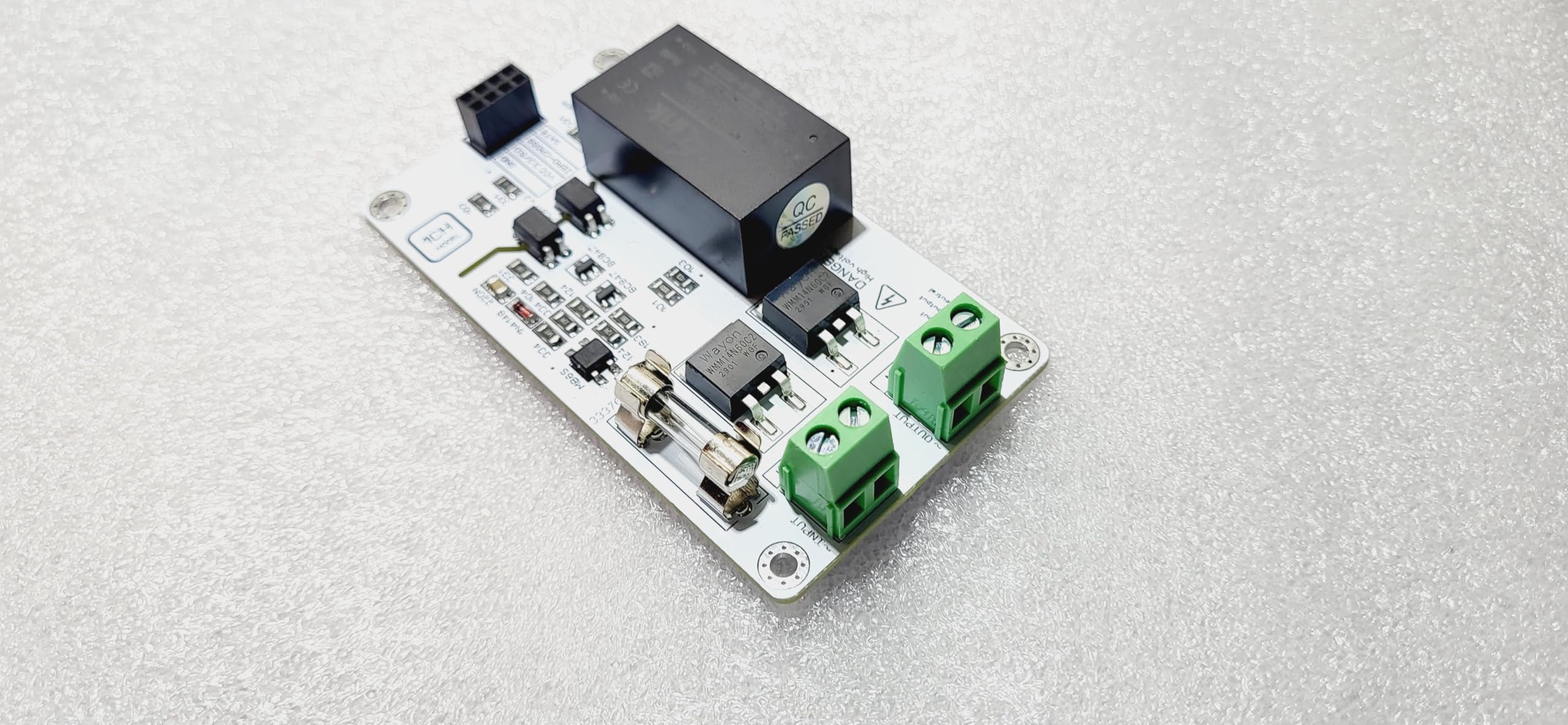
The MOSFET Trailing Edge AC LED Light Dimmer by IotMug offers advanced, flicker-free dimming control compatible with incandescent and dimmable LED bulbs. Supporting up to 500W output and multiple dimming methods, it integrates seamlessly with popular microcontrollers like Arduino, Raspberry Pi, ESP8266, and ESP32. Compact and versatile, it’s designed for professionals and DIYers seeking precise, stable lighting control in any smart home or project setup.
| ASIN | B0CL3RLKLC |
| Actuator Type | electronic" or "solid-state |
| Best Sellers Rank | #927,905 in Tools & Home Improvement ( See Top 100 in Tools & Home Improvement ) #1,517 in Dimmer Switches |
| Brand | IotMug |
| Circuit Type | 1-way |
| Compatible Devices | Arduino, Raspberry Pi, ESP8266, ESP32, Adafruit boards |
| Connectivity Protocol | X-10 |
| Connector Type | Screw |
| Contact Material | Metal |
| Contact Type | Normally Open |
| Control Method | App |
| Control Type | Advanced |
| Current Rating | 5 Amps |
| Date First Available | October 16, 2023 |
| Item Weight | 1.23 ounces |
| Item dimensions L x W x H | 1.97 x 3.54 x 0.47 inches |
| Item model number | Mosfet Trailing Edge Dimmer |
| Manufacturer | IotMug |
| Number of Items | 1 |
| Number of Positions | 1 |
| Operating Voltage | 110 Volts |
| Operation Mode | automatic |
| Product Dimensions | 1.97 x 3.54 x 0.47 inches |
| Terminal | Through Hole |
| Unit Count | 1.0 Count |
| Wattage | 5 watts |
E**N
Good product, excellent support
Works well and can implement any dimmer waveform. Excellent service, would buy from this vendor again. Here is a version of the script for the ESP32-S3 using the latest timer API (that was changed in a way that breaks the existing timer based scripts) #define GATE 5 #define ZERO_CROSS_PIN 4 #define FREQ 8333 hw_timer_t *gateTimer = NULL; //timer 1Mhz resolution int dimmerLevel = 0; int timerActive = 0; long counter = 0; long counter2 = 0; long start = 0; long end = 0; void ARDUINO_ISR_ATTR ZeroCrossISR() { if (dimmerLevel > 0 && timerActive == 0) { digitalWrite(GATE, HIGH); timerAttachInterrupt(gateTimer, &TimerISR); //attach callback timerAlarm(gateTimer, ((FREQ * dimmerLevel) / 4096), true, 0); timerWrite(gateTimer, 0); //timerRestart(gateTimer); timerStart(gateTimer); timerActive = 1; counter++; //start = micros(); } else digitalWrite(GATE, LOW); delayMicroseconds(100); // debounce zero-crossing} } void ARDUINO_ISR_ATTR TimerISR() { digitalWrite(GATE, LOW ); //end = micros(); timerStop(gateTimer); timerActive = 0; counter2++; } void setup() { Serial.begin(9600); while (!Serial){} pinMode(ZERO_CROSS_PIN,INPUT_PULLUP); pinMode(GATE,OUTPUT); digitalWrite(GATE, LOW); attachInterrupt(ZERO_CROSS_PIN, &ZeroCrossISR, FALLING); gateTimer = timerBegin(1000000); timerAttachInterrupt(gateTimer, &TimerISR); } void loop() { /* Serial.print("Still running... "); Serial.print(counter); Serial.print(", "); Serial.print(counter2); Serial.print(" Microsecs = "); Serial.println(end - start); */ dimmerLevel = 0; for (int i = 0; i < 4096; i += 50) { dimmerLevel = i; } for (int i = 4090; i >= 0; i -= 50) { dimmerLevel = i; } delay(5000); }
J**.
It works great, but
The code offered will not compile! Customer Service??? Non existent. I developed this code that works as of 10/11/24 Good Luck! // Pin Definitions const int zero_cross_pin_ip2 = 2; // Input from zero-crossing detector const int mosfet_op9 = 9; // MOSFET gate control (PWM output) int dimming_level = 255; // Dimming level (0-255), adjust for brightness // Time per half cycle for 50Hz = 10000 microseconds (10ms), for 60Hz = 8333 microseconds (8.33ms) int AC_half_cycle = 72000; // Adjust for 50Hz or 60Hz AC - 72000 works best for my application // Zero crossing interrupt handler volatile bool zeroCrossDetected = false; void zeroCrossISR() { zeroCrossDetected = true; } void setup() { pinMode(mosfet_op9, OUTPUT); pinMode(zero_cross_pin_ip2, INPUT); // Attach interrupt to zero-crossing pin (RISING signal) attachInterrupt(digitalPinToInterrupt(zero_cross_pin_ip2), zeroCrossISR, RISING); Serial.begin(9600); delay(234); Serial.println("dimmer_AI2"); delay(234); } // end setup void loop() { if (zeroCrossDetected) { zeroCrossDetected = false; // Map dimming level (0-255) to time delay (0-AC_half_cycle) int delayTime = map(dimming_level, 0, 255, AC_half_cycle, 0); // Wait for the delay time (to control phase cut) delayMicroseconds(delayTime); // After the delay, turn the MOSFET ON to allow current to pass for the rest of the cycle digitalWrite(mosfet_op9, HIGH); // Keep MOSFET ON for the remaining cycle delayMicroseconds(AC_half_cycle - delayTime); // Turn MOSFET OFF at the end of the half-cycle digitalWrite(mosfet_op9, LOW); } // Optionally, update dimming level from Serial input for dynamic control char i_read = 'x'; int enter = 0x0A; int got_serial = false; char heres_what_i_read = ']'; if (Serial.available() > 0) { i_read = (Serial.read()); if (i_read != enter) { heres_what_i_read = i_read; } if (heres_what_i_read == 'd') { dimming_level = dimming_level - 10; Serial.print("dimming_level "); Serial.println(dimming_level); } if (heres_what_i_read == 'u') { dimming_level = dimming_level + 5; Serial.print("dimming_level "); Serial.println(dimming_level); } } } // end loop
M**L
Good for my test bench
Preformed as intended and easily turned in to a tester with additional parts. It just Works
Trustpilot
1 month ago
1 week ago